No, not cutting it up, that comes later. Below is the glued frame with DP420 and glass microsphere putty applied to create fillets at the joints. The tiny 50 micron hollow glass spheres make the epoxy thick and easier to work with. These will be sanded smooth prior to layup. The blue tape is flash breaker tape and marks the end of where the "lugs" will be for this test frame.
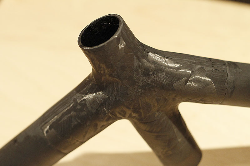
First the head tube joint.
Then the BB...
And the complete frame...
The frame currently weighs 957g. It was 452g as a finished front triangle and 952g prior to adding the fillet paste. I think 5g is worth it for smoother flowing joints. The frame alignment out of the jig is pretty good as well. The head tube is out by 0.012" of the 6.5" head tube length (should be better). The seat tube is dead on at 0.004" over 20". The rear wheel sits straight and the dropout spacing is 129.25mm which is a little under 130mm, I'd rather be 0.5mm over.
Wednesday, January 05, 2011
Sunday, January 02, 2011
Glue Time!
I skipped over gluing the front triangle together. My gloves were too sticky to touch the camera. Below are the dropouts sanded rough, cleaned with isopropyl alcohol then slathered in DP420. The same thing was done to the inside of the chain and seat stay ends.
Here is the finished glued BB joint. The tubes around the joints were sanded to bare carbon and cleaned with alcohol in preparation for wrapping with prepreg.
Same thing at the seat tube joint.
The shop was about 10C today so I have the rear end "curing" in front of the heater. It only blows warm air...nothing catching fire or melting.
Next step is to fillet the joints with fairing compound, sand and shape them.
Mitering Stays
I could not use my normal stay mitering fixture with the carbon rear end. Luckily whoever designed it was thinking and made the top and bottom edges parallel for the first 6" making it relatively easy to hold in the mill vice.
Here is another shot showing the belt sander attachment and shop vac clamped in place to suck away the dust.
Thursday, December 30, 2010
Test Frame
It's time to build a test frame. I collected some appropriate tubes and substituted some 1.75" OD for the BB and head tube. Step one (well, actually about step 17) is to miter the tubes to fit in the jig.
Here I fit the head tube to the jig with the new oversize locating cones.
Below you can see the mill mounted belt sander in action cutting the DT to HT joint. I hold a shop vac with a fine particle bag installed next to the belt/tube to catch the carbon and epoxy dust.
I built the mitering fixture so the tubes could be removed with both the holding blocks locked in place, one on each end of the tube. This allows me to test fit tubes in the jig and return them to the mill in the same location if further cutting is required. Here you can see the DT with it's holding block in the jig.
The finished BB joint with the other miter block shown.
The front triangle fit in the jig. Next step will be to miter and fit the rear end.
Sunday, December 12, 2010
Break Time II
After the side load I tested the in plane bending (trying to pull the joint apart in the the plane of the frame). I used split blocks to support the ends of the tube and a 4' solid steel pry bar to apply the load.
I applied almost 1/2 my body weight to the joint about 4 feet from the support block. So, the joint was under 300+ ft-lb of torque. After alternating this load in opposite direction a few times there was a cracking sound and this small flap of carbon pulled free. Also, a small crack curved under and along the joint fillet..
One good hard heave (probably over 400 ft-lb) and the joint cracked further.
Eventually if failed completely...
Break Time
First you'll notice the custom patent pending "distributed loading system" employed for this test. I stood on the test joint suspended between two frame tube blocks. This resulted in 170lbs being applied. Nothing happened. I then pulled up on the nearby work bench and applied more load...and more until I could not pull any harder. Other than a tiny deflection there was no damage. Repeating this later with a bathroom scale sent the needle off dial over 340lbs. So, 350lb sideways load test passed.
Sunday, December 05, 2010
Finished Finishing?
Epoxy "Painted" Joint
Friday, December 03, 2010
Sanded Joint
I quickly sanded the joint to take off the epoxy flash and the high points etc. I didn't take too much off so I would not cut away fibers.
I'm going to "paint" the joint with clear epoxy and sand that to get it cosmetically smooth. The top side of the joints turned out well with little sanding. The underside had a void in one area that will have to be filled.

Once I make it all pretty it's time to break it...


Once I make it all pretty it's time to break it...
Unsanded Joint
Here is the joint after pulling off the vacuum bag and unwrapping the release cloth and tape. Seems to be good compression this time with a just a few small voids at the root of the underside fillets.
This side (that was facing up in the oven) did not seem to be as compressed. It lacks the even pattern from the release cloth you can see on the other side. It appears well consolidated though.


Thursday, December 02, 2010
Vacuum Bagging
After reading about Nick Crumpton's methods here
http://www.velocipedesalon.com/forum/f26/carbon-building-18058.html
I decided to try to bag the whole joint this time and not seal off on the tubes. You can see little wood caps taped on the tubes I put there to keep the bag from sucking in and breaking.
This is at 20 inHg and it went to 26.5 inHg before it went in the oven.
Here it is resting on a block of wood ready to bake.
http://www.velocipedesalon.com/forum/f26/carbon-building-18058.html
I decided to try to bag the whole joint this time and not seal off on the tubes. You can see little wood caps taped on the tubes I put there to keep the bag from sucking in and breaking.


Seat Cluster Test
I'm trying larger fillets (Aeropoxt Light fairing compound) over the glued joints to see how the carbon layup works with them.
Here are the first few layers of 150g/m^2 unidirectional prepreg being applied.

And here is a the finished joint. I tried to be aware of the final cosmetics of the joint as I went. Time will tell how it looks and performs after it come out of the oven.


And here is a the finished joint. I tried to be aware of the final cosmetics of the joint as I went. Time will tell how it looks and performs after it come out of the oven.

Sunday, November 21, 2010
Out of the Oven
Here is the joint out of the oven. It sat at 200F for 2 hours after ramping up for 30 minutes. The bag, release ply etc peeled off fairly clean but I'll use some flash break tape next time to keep the tubes clean in the first place. You can see in the photo below I had some bag pressure issues. A small hole developed right at the inlet tube and the pressure was 15-20inHg (or about 10pis) when I it took it out of the oven. The shiny area is where the release ply was not being pressed into the joint.

On the top side though, the joint is well compacted and solid. I found that tapping on the joints tells you a lot. You can tell the uncompressed areas by sound alone.

While not pretty yet (these are un-sanded) and not fully compacted the main tube joints feel strong and stiff. Destructive testing and cutting it apart will tell the whole story though.

Joint Test Vacuum Bag
Here is a BB test joint I've prepped for the oven. I used 3 pieces of Stretchlon 250 bag material and 350F rated bag tape. Under the tape is release cloth with a very fine weave, then the carbon prepreg layers. You can see the UHMW plugs I use in the BB to run the bag and seal tape onto.

It took about 10 minutes to get all the leaks sealed and I was able to pull 26mmHg on the pump. The bag did it's job and stretched nicely into the fillets. The release cloth appears to be enough of a bleed layer on a bag this small, everything was pulled down tight.

It took about 10 minutes to get all the leaks sealed and I was able to pull 26mmHg on the pump. The bag did it's job and stretched nicely into the fillets. The release cloth appears to be enough of a bleed layer on a bag this small, everything was pulled down tight.

Friday, November 05, 2010
Head Tube Cure and Finish
After applying 10 layers on the mandrel I used the lathe to hold the it in place and slowly turned it by hand to apply the release coated shrink tape. I'm carefully overlapping 75% with the previous turn for better compressive force and a smoother ridge free finish.
Into the oven it goes...

Here it is straight out of the oven with the shrink tape removed. Notice the left hand end, that's where the masking tape holding the shrink tape in place let go and allowed it to slip. Good thing I made the tube a little longer than required.

Back in the lathe I hand wet sand the outer surface and square the ends with the lathe tooling. Wet sanding eliminates the dust issue (as long as you protect the lathe from the splashing).

The finished headtube. It is ridiculously stiff and weighs 50.3 g.

Head Tube Layup
After calculating the thermal expansion of UHMW for the temperature delta of the cure process I decided to layup a headtube for Chris King InSet headset press fit ID of 44mm.
You can see the layers below, 10 in total, alternating between 0 deg and 90 deg.

The next two photos show the wrapping process as the carbon sticks to the previous layer and the backer is peeled away. Working in the shop around 50F I had to use a heat gun to increase the tack level of the prepreg in order to get the wraps to stick and conform.

The finished layup ready to shrink tape.
You can see the layers below, 10 in total, alternating between 0 deg and 90 deg.

The next two photos show the wrapping process as the carbon sticks to the previous layer and the backer is peeled away. Working in the shop around 50F I had to use a heat gun to increase the tack level of the prepreg in order to get the wraps to stick and conform.


Thursday, October 07, 2010
Tube ID
Press30 Tube
UHMW Mandrel
I tried unsuccessfully to lay up a head tube on a turned polished aluminum mandrel. Even with 3 layers of high temp release wax, post cure the carbon would NOT come off the mandrel. Back to the drawing board. Next I conducted a test using UHMW as a mandrel. It has a higher coefficient of thermal expansion than aluminum and nothing sticks to it (at least not epoxy). It turns up in the lathe nice and smooth and the 250F cure temp has no lasting effect on it.

Subscribe to:
Posts (Atom)